The ability to trap an object—whether a single atom or a macroscopic entity—affects fields as diverse as quantum optics1, soft condensed-matter physics, biophysics and clinical medicine2. Many sophisticated methodologies have been developed to counter the randomizing effect of Brownian motion in solution3, 4, 5, 6, 7, 8, 9, 10, but stable trapping of nanometre-sized objects remains challenging8, 9, 10. Optical tweezers are widely used traps, but require sufficiently polarizable objects and thus are unable to manipulate small macromolecules. Confinement of single molecules has been achieved using electrokinetic feedback guided by tracking of a fluorescent label, but photophysical constraints limit the trap stiffness and lifetime8. Here we show that a fluidic slit with appropriately tailored topography has a spatially modulated electrostatic potential that can trap and levitate charged objects in solution for up to several hours. We illustrate this principle with gold particles, polymer beads and lipid vesicles with diameters of tens of nanometres, which are all trapped without external intervention and independently of their mass and dielectric function. The stiffness and stability of our electrostatic trap is easily tuned by adjusting the system geometry and the ionic strength of the solution, and it lends itself to integration with other manipulation mechanisms. We anticipate that these features will allow its use for contact-free confinement of single proteins and macromolecules, and the sorting and fractionation of nanometre-sized objects or their assembly into high-density arrays.
Figures at a glance
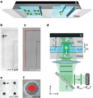
Figure 1: Pictorial overview of the device and experimental set-up. 
a, Illustration of the fluidic device with nanostructured slit surfaces. b, iSCAT image of a gold particle confined by a ‘groove’ nanostructure. Destructive interference between the light scattered by the particle, Esca, and the reflected field, Eref, causes the particle to appear dark against a light background. c, Trajectory of particle motion (red) along a groove overlaid on a scanning electron micrograph (SEM) of the underlying surface topography. d, Device and optical set-up for iSCAT (not to scale), highlighting dimensions that are important in the confinement interaction: slit height, 2h = 200 nm; nanostructure diameter or width, D = 100–500 nm; nanostructure depth, d = 100 nm. ls, lw, physical path lengths in silicon dioxide and water, respectively. e, f, iSCAT image of single gold particles confined by ‘pocket’ nanostructures, and the trajectory of a single particle (red) overlaid with an SEM of the underlying surface topography.
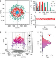
Figure 2: Transverse and axial confinement of a 100-nm gold particle by pocket nanostructures. 
a, Transverse (x–y) positions of single 100-nm gold particles trapped by pockets of diameter D = 500 nm (red) and 200 nm (blue) in 7 × 10⁻⁵ M electrolyte and D = 500 nm in 0.1 mM NaCl (green). b, Radial probability histograms averaged over about ten different trapped particles in each case. P(r) was defined according to
 . The displayed distribution was rescaled so that Pmax(r) = 1 (error bars, s.e.m.). A Gaussian fit to P(r) for D = 200 nm (black curve) yields a radial trap stiffness of kr = 0.02 pN nm−1. c, Intensity–time traces for a single particle trapped by a D = 500 nm pocket in 7 × 10⁻⁵ M electrolyte (red) and for the background (black). The intensity fluctuation of the particle reflects its motion in z (a.u., arbitrary units). d, Three-dimensional scatter plot of a particle confined by a D = 500 nm pocket in 7 × 10⁻⁵ M electrolyte (z scale exaggerated). Insets, iSCAT images of the particle highlighting the modulation of contrast at different axial positions. e, Histogram of axial displacement revealing a mean levitation height of z = 52 ±2 nm and an axial trap stiffness of kz = 0.027 pN nm−1.
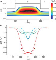
Figure 3: Electrostatic potential in a topographically structured fluidic nanoslit. 
a, Two-dimensional electrostatic potential obtained by solving the Poisson–Boltzmann equation for an axisymmetric pocket of diameter D = 500 nm and depth d = 100 nm, for C = 7 × 10⁻⁵ M electrolyte in a slit of height 2h = 200 nm. The experimental data of Fig. 2d is presented to scale as black symbols overlaid on the calculated potential distribution. b, Electrostatic energy of a point charge of q = −120e as a function of r along a contour of minimum axial (z) electrostatic energy. Red curve: D = 500 nm, C = 0.07 mM; blue curve: D = 200 nm, C = 0.07 mM; green curve: D = 500 nm in 0.1 mM NaCl (total ionic strength, C = 0.17 mM). Overlaid squares represent the local potentials u(r) derived from the experimentally measured P(r) from Fig. 2b. Experimental data for large r are not provided because the probability of finding the trapped particle far from the potential minimum falls off exponentially, leading to rare occurrences.
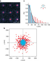
Figure 4: Trapping single lipid vesicles. 
a, Image of single fluorescent negatively charged vesicles trapped in arrays. b, Transverse spatial sampling of single vesicles trapped by D = 500 nm (red) and D = 200 nm (blue) pockets in 4 × 10⁻⁵ M electrolyte (data from five different vesicles overlaid in each case). c, Radial probability density histograms P(r) for the data shown in b. A Gaussian fit to P(r) for D = 200 nm (black curve) yields a radial trap stiffness of kr = 0.01 pN nm−1.
